
Talk:Hartley oscillator
| This article is rated C-class on Wikipedia's content assessment scale. It is of interest to the following WikiProjects: | |||||||||||
| |||||||||||

Cleanup?[edit]
This is listed on cleanup for expansion, and I can't see why. It looks excellent to me other than some minor grammar issues.
There are certainly things that could be added, mainly historical things like who was Hartley, some of the many valve circuits that used this oscillator design, and more recent applications. But I can't help wondering, if someone knows of more material that belongs here, why they just don't add it themselves? I'll try to dig out some history myself. Andrewa 00:29, 16 Mar 2004 (UTC)
- I added part of the circuit of the Scott 310E receiver, and a tiny little bit about its usage. TuringBirds 22:06, 7 Sep 2006
- I Listed this, as it looked like the single sentences for structures and advantages/disadvantages could probably be expanded, and explained, rather than that there are particular grammatical or other errors in the text. I don't know of more material that belongs here, but it seemed likely, when I looked at it, that there was some, but I don't know enough about the subject to add anything, so added it to cleanup, so if there was anything useful to add, someone who knows about the subject can add it. Silverfish 16:54, 16 Mar 2004 (UTC)
- I think that's just a matter of the style in which it's written. I could easily rewrite it in essay fashion, but for this material IMO the existing style is fine. Andrewa 01:48, 17 Mar 2004 (UTC)
- I'll defer to you on this, as you seem to know more about the subject than me. Silverfish 12:49, 17 Mar 2004 (UTC)
The article starts by saying that the Hartley oscillator is a "... type of inductively coupled oscillator ...". This is not true. Granted the design is usually implemented using a tapped inductor, but there is no requirement to do so. The oscillator design is just as valid if there is no mutual coupling beween the two parts of the inductor. The circuit works by deriving the feed back from the tapping point, something that is will still work with no mutual coupling. This is analagous to the Colpitts oscillator where there is no mutual coupling between the capacitors.
There is a lot of fundamental information missing that could make it a better entry for both novice and experienced students of electronics. Since this is an oscillator I would like to see some maths describing the operation of all oscillators. There is no reference made to the two fundamental building blocks of oscillators, namely a tuned circuit and amplifier. Coupled to this the Barkhausen criteria for oscillators is also a necessity.
Information of a more technical nature about how oscillation is started in the LC circuit at the moment power is applied and how the amplifier reacts to this is is also a must have for any serious discussion of oscillators. Positive feedback loops should be discussed and how it is special to oscillators. Also, sketches of the Hartley oscillator utilising different amplifier topologies with the pros and cons of each will be useful.
In short, there is a lot of superficial information about the Hartley oscillator available on the web, but nothing of substance. The Wikipedia entry should be the de facto standard. — Preceding unsigned comment added by 208.114.124.241 (talk) 04:39, 4 June 2012 (UTC)
Scott 310E oscillator schematic[edit]
I think the tube based Scott 310E oscillator should be replaced with a more modern BJT or FET version. The audience for these articles probably knows very little about tubes (myself included) and the schematic is more confusing than helpful. -Roger 20:00, 31 October 2007 (UTC)
- but where did the circuit go? It is referred to in the text "(see the Scott circuit below)" but only the simple, without grid leak, version is shown. — Preceding unsigned comment added by Maitchy (talk • contribs) 20:24, 25 November 2013 (UTC)
Missing item[edit]
Presumably the oscillator requires either a valve or a transistor but there is no mention of this in the article. Biscuittin (talk) 23:09, 1 March 2008 (UTC)
Disadvantages[edit]
There is much hearsay that the circuit is not suitable to generate a pure sine wave. This is simply not true for a properly designed circuit; it depends on the place where the signal is obtained. The signal on the coil tap is rather good, if the amplifier is not too much overloaded, i.e. the tap is small enough; then, the source is of relatively low amplitude and impedance. Or a low capacity buffer can to be used at the hot end of the coil (see the EDN article, where the buffer is coupled to the gate and not the source, as is often shown elsewhere).
Because using the LC circuit as a source gives problems with (capacitive) load and stability, often the current of the amplifier is used directly or indirectly. This waveform, however, is normally far away from a sine wave. But this is true for practically every LC oscillator, unless its gain is controlled by amplitude stabilisation.
Otherwise, I would be interested in reliable references.
-- Rainglasz (talk) 09:54, 10 December 2008 (UTC)
Cleanup still required?[edit]
I cannot see that cleanup is still required. Maybe the article could still be improved; but the cleanup mark signals from my understanding that the article is still not mature, which is not my impression.
So I would like to remove the cleanup mark. Is that ok? Otherwise, I would like to have some hints in this discussion page.
- Well, having a deeper look reveals for me several points for improvement:
- * The pictures are not at the right place
- * The pricipial circuit should use a FET to be closer to the original circuit
- * The patent drawing should be accompanied by a modern variant and explained
- * contents should be on top
- etc etc
- Rainglasz (talk) 18:58, 20 December 2009 (UTC)
- First round for the easier changes done.
- Used reference to LC circuit instead of tank circuit; both lead to the same article, but the latter looks a bit colloquial for a non-native speaker.
- Rainglasz (talk) 19:53, 20 December 2009 (UTC)
Rainglasz (talk) 16:48, 20 December 2009 (UTC)
Basic Theory[edit]
The original text placed too much emphasis on the requirement of an inductive feedback voltage divider. This is very misleading as the Hartley oscillator does not require such a connection. Kevin aylward (talk) 16:32, 26 December 2012 (UTC)
Circuit is wrong?[edit]
This circuit looks wrong to me. It appears that the JFET's junction will be forward-biased during at least part of the cycle. Isn't that usually a no-no? Also, I notice that most other JFET circuits on the internet have this same flaw. I'm beginning to wonder whether everyone else is wrong or I was just taught wrong. Would it be possible to make this a depletion-mode MOSFET instead to solve the problem? Xezlec (talk) 19:56, 20 January 2013 (UTC)
- As a simplified circuit, it's probably OK. The forward bias on the junction would work as an amplitude limiter; amplifier gain would decrease. Some real circuits may have a form of grid leak bias, but I think the junction is still overdriven. It's been too long. Some circuits use a diode to ground to avoid forward biasing the junction, but those designs may have poor noise performance. Glrx (talk) 01:56, 5 February 2013 (UTC)
- I added a practical example. I used the grid leak from the original schematic to give the JFET proper bias, but I did not include the diode. There is no "correct" solution. AndreAdrian (talk) 21:26, 19 February 2024 (UTC)
- Simulation with LTSpice gives easy oscillation and breadboarding of circuit was a success after I increased C2 from 4.7pF to 10pF. AndreAdrian (talk) 14:36, 20 February 2024 (UTC)
Several errors[edit]
The article appears to contain some significant errors:
1 The simplified circuit is described as providing feedback from the inductor tap, the source of the FET. Since the gate is the input terminal to the FET, that surely is the feedback 'output' from the LC circuit. The tap is the input in this configuration, driven by the low-impedance source;
2 The polarity marking on the op-amp version is reversed;
- I really wonder whether this opamp circuit, even after correction (it would not work properly as-is) is widely recognised as truely "Hartley"... meanwhile a common-base version of tapped-coil oscillator is quite often referred to as "Hartley" yet not mentioned here... until now. Maitchy (talk) 21:52, 25 November 2013 (UTC)
3 The original patent confirms that the Hartley oscillator, like its Colpitts analogue, relies on reactive phase inversion, not inductive coupling. Kevin Aylward, above, is therefore right to challenge this confused wording. Using inductive coupling, only one inductor is required, with a close-coupled feedback winding - an entirely different animal. Of course, both forms of feedback can be present in the same circuit - a hybrid case.
4 I would be happier to see a clearer statement of the requisites for an oscillator - the combination of a gain device (with intrinsic feedback that is normally negative); a mechanism to provide phase inversion, to overcome that negative feedback and make it oscillate, and something to define the frequency. If you feel picky, add parts to set operating conditions and the maths to define whether oscillation starts and its amplitude if it does. — Preceding unsigned comment added by Mjbtnc (talk • contribs) 16:36, 29 April 2013 (UTC)
Circuit operation[edit]
I don't have time to go into it, but the simplified circuit description has many flaws. If the common drain amplifier is a voltage controlled voltage source, then it would destroy the tank Q. Tap selection is much more involved. JFET will limit amplitude. JFET input Z inf only at low freq. Glrx (talk) 17:39, 14 August 2015 (UTC)
Impractical circuit schematics[edit]
I don't think any of the circuits presented in this article are practical. The common-drain JFET implementation does not show biasing (file:Hartley osc.svg). The op-amp implementation does not show gain (file:Oscillator hartley opamp.svg). The electronic oscillator article has an article that also lacks biasing (file:Oscillator comparison.svg). I simulated each one of the circuits in PSpice without any success. If any of you had success, I would like to know how you implemented the missing details and what component sizes you used.
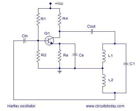
The only circuit I got to work is a circuit I found on the Internet (http://www.circuitstoday.com/wp-content/uploads/2009/10/hartley-oscillator.png).
I think this article should show practical circuits. The circuits should be simple and they should not hide important details like biasing and gain.
ICE77 (talk) 20:19, 14 August 2015 (UTC)
- I don't see any fundamental problem with file:Hartley osc.svg. It may forward bias the gate, but that should just impact amplitude and stability. Choosing the product of drain current and load resistance less than 0.5 V would keep things in reasonable shape.
- The op amp implementation file:Oscillator hartley opamp.svg has the inputs backwards (see above), the low-Z output should drive the tap, and the design should not use an infinite gain op amp. The figure should be nuked.
- I don't see any problems with file:Oscillator comparison.svg; they should work. One resistor biasing is not the best, but the high Z collector drives top of tank and lower Z input is taken from tap.
- The .png is the same as the third .svg but uses more robust three resistor biasing with Ce bypass. If you can make the .png work, then you can make the third .svg work.
- I'm not so sure that practical circuits should be shown. WP is an encyclopedia and not tutorial about circuit design. There are many subtle details to real circuits.
- Glrx (talk) 21:42, 14 August 2015 (UTC)
Glrx, if the second circuit (file:Oscillator hartley opamp.svg) has the inputs swapped then the image is clearly wrong and it should either be removed or fixed because it only leads to confusion.
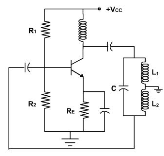
I spent some more time simulating and I was able to get another circuit I found on the Internet to work. Since both Hartley and Colpitts are described as dual of each other and appear to have an inductor at the collector of their BJTs, I figured that the new circuit I found is more appropriate (http://www.expertsmind.com/CMSImages/1598_hartley%20oscillator.png).
I am not saying that Wikipedia should be the place to find all the details about circuits but this place should not propose impractical circuits, let the reader assume things he or she does not know and, most of all, present bad examples of circuits.
ICE77 (talk) 00:57, 15 August 2015 (UTC)
The impedance of an inductor depends on frequency. The impedance of a resistor is independent of frequency. I don't think there is a little difference. If there is I would like to know what is the small difference and what is the purpose of using an inductor or a resistor on the collector of a BJT-implemented Hartley or Colpitts oscillator?
ICE77 (talk) 23:39, 26 August 2015 (UTC)
- I added a practical circuit. But, oscillators are hard to simulate and even harder to build. For example: the load resistor in simulation is 3 kiloohm, but zero picofarad capacitance. If you use your oscilloscope probe you have 1 megaohm (no problem) but 20 picofarad capacitance (can be a problem). AndreAdrian (talk) 21:36, 19 February 2024 (UTC)
External links modified[edit]
Hello fellow Wikipedians,
I have just modified one external link on Hartley oscillator. Please take a moment to review my edit. If you have any questions, or need the bot to ignore the links, or the page altogether, please visit this simple FaQ for additional information. I made the following changes:
- Added archive https://web.archive.org/web/20080704153045/http://www.edn.com/article/CA6343253.html to http://www.edn.com/article/CA6343253.html
When you have finished reviewing my changes, you may follow the instructions on the template below to fix any issues with the URLs.
This message was posted before February 2018. After February 2018, "External links modified" talk page sections are no longer generated or monitored by InternetArchiveBot. No special action is required regarding these talk page notices, other than regular verification using the archive tool instructions below. Editors have permission to delete these "External links modified" talk page sections if they want to de-clutter talk pages, but see the RfC before doing mass systematic removals. This message is updated dynamically through the template {{source check}} (last update: 18 January 2022).
- If you have discovered URLs which were erroneously considered dead by the bot, you can report them with this tool.
- If you found an error with any archives or the URLs themselves, you can fix them with this tool.
Cheers.—InternetArchiveBot (Report bug) 22:07, 30 October 2017 (UTC)
General approach to article[edit]
It is not clear to me how this article should approach the subject. I understand it is not intended to be a tutorial. Do any actual real-world implementations belong here? Or should the approach be a generic one -- for example a circuit model containing only a generic transconductance for instance?
Or should it contain both? First a presentation of a generic circuit, not specific to any particular technology, followed by some examples of implementation in various technologies (e.g. vacuum tube triode, jfet, bipolar transistor, op-amp, etc)?
It seems to me the presentation of a generic circuit with a VCCS (transconductance) can be used to show not only the operation of the circuit, but to analyze the necessary conditions for oscillation to occur (e.g. RHP poles in a transfer function).
Anyone interested in seeing that? 142.254.37.91 (talk) 18:01, 7 March 2023 (UTC)